
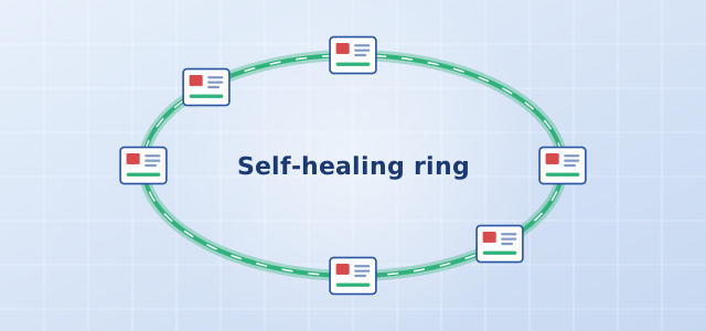
A solar or wind plant can have anywhere from a few dozen to several hundred box-type transformers, spaced hundreds of meters to several kilometers apart. Copper cable cannot cover those distances reliably and is vulnerable to lightning and electromagnetic interference, so site communication is almost always built on optical fiber. The most common topology is the self-healing fiber ring.
1. What Is a Self-Healing Ring?
Connect the box transformer monitoring units in one area end to end with fiber-optic cable, then bring both ends of the chain back to a ring switch in the control room, and you have a ring. In normal operation, data travels in one direction while the other path stands by. If the cable is cut at any point on the ring, or a unit loses power, the ring protocol switches traffic to the other direction within a very short time, and the remaining units stay online. That is what "self-healing" means.
The benefit: for the cost of a single return cable, you gain link redundancy. A ring uses far less cable than running a dedicated fiber from every box transformer to the control room (star topology), and it is far more reliable than a single daisy chain (bus topology).
2. Why Integrated Fiber Ports Matter
The traditional approach was to install a separate industrial fiber switch in every box transformer. AOYI's NSA3 and NSA2 Smart Station Monitoring Units have two built-in fiber ports, so the unit itself is a node on the ring. This eliminates the separate switch, its power supply and wiring, and removes one more point of failure. The fiber ports use ST connectors and support transmission distances of up to 50 km.
3. How Many Units per Ring?
More nodes per ring means each ring covers more box transformers and uses less cable. But if two breaks occur at once, more units are affected and troubleshooting takes longer. In practice, rings are usually divided by collector line: the box transformers on one collector line form one ring. This matches the maintenance boundaries of the primary system and keeps operations intuitive. The exact number of units per ring should be set based on the ring switch's capacity, the protocol polling cycle and the owner's requirements.
4. Installation and Commissioning Checklist
- Cable routing: Avoid running the outgoing and return legs of the ring in the same trench or conduit. Otherwise a single excavation can cut both legs at once, defeating the purpose of the ring.
- Splicing and loss: Record every splice point. During acceptance, measure link loss with an OTDR or optical power meter and make sure there is adequate margin.
- Patch cords and connectors: Do not bend fiber patch cords too tightly inside the box transformer, and clean the end faces of ST connectors after every mating.
- Port mapping: Label how fiber port 1 and fiber port 2 on each unit connect upstream and downstream. Without labels, locating a break later becomes very difficult.
- Self-healing test: During acceptance, deliberately disconnect any one cable segment on the ring, confirm that every unit remains online in the monitoring system, then restore it.
5. Detecting Breaks During Operation
Because a single fault on a ring does not interrupt communication, it is easy to overlook. We recommend configuring a "ring open" alarm for each ring in the monitoring system, or regularly checking the fiber port status of each unit. Repair any single break promptly, before a second fault takes an entire section offline.
For network design references, see our smart monitoring solution for renewable power plants, or download the technical manuals for each product.