
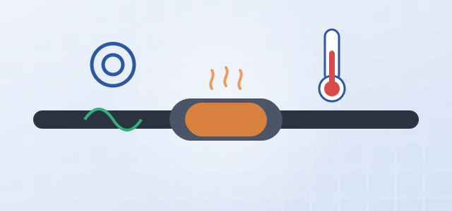
In a renewable power plant, each box-type transformer connects to the collector line through medium-voltage cable. The cable itself is very reliable, but cable terminations and splice joints are made on site, so their quality depends heavily on workmanship. Cable insulation, meanwhile, gradually degrades with age, moisture and mechanical damage. A failure at either point can, at best, take one box transformer out of service and, at worst, start a fire or trip an entire collector line.
1. Why Do Cable Joints Overheat?
- Rising contact resistance: Poor crimping, loose bolts and oxidized contact surfaces all increase contact resistance, so the joint heats continuously whenever current flows.
- Load swings and thermal cycling: Solar output is high during the day and zero at night. Repeated expansion and contraction gradually loosens the joint.
- A vicious cycle: Higher temperature accelerates oxidation, which raises contact resistance further, and can eventually burn out the joint.
Manual infrared inspection can only be done periodically, and joints behind box transformer cabinet doors often cannot be seen without a power outage. Online temperature monitoring shows temperature and trends continuously, catching problems before a joint actually fails.
2. Why Wireless Temperature Sensing?
A cable joint sits at high potential, so a temperature probe cannot be wired back to a device on the low-voltage side. The usual solution is to mount a wireless temperature sensor on the joint, which transmits readings to a nearby receiver. AOYI's NSA3 Smart Station Monitoring Unit has a built-in 433 MHz wireless access point that receives cable-joint temperature directly. The address, alarm threshold and reporting interval of each sensor can be configured, and an alarm is raised on over-temperature.
3. What Does Grounding Current Tell You?
The metallic sheath (shield) of a cable must be reliably grounded. In normal operation, only a very small current flows in the grounding conductor. When the insulation absorbs moisture and deteriorates, the sheath is damaged and grounded at multiple points, or the grounding system is faulty, the grounding current rises noticeably or changes abnormally. Continuously monitoring the magnitude, rate of change and waveform of the cable sheath grounding current provides a basis for assessing insulation condition.
The NSA3 monitors cable sheath circulating current online through one grounding current input. It samples and stores historical current data, analyzes insulation condition from the current curve, and raises an alarm when limits are exceeded.
4. Putting the Data to Use
| Symptom | Possible cause | Recommended action |
|---|---|---|
| One joint runs noticeably hotter than similar joints | Poor contact or crimping defect | Schedule an outage for inspection; retighten or remake the joint |
| Joint temperature rises ever more steeply with load | Contact resistance gradually increasing | Place on a watch list and repair at the next opportunity |
| Grounding current rising steadily | Insulation degradation, moisture ingress or sheath damage | Diagnose further with an insulation resistance test |
| Sudden change in grounding current | Grounding system fault or mechanical damage | Inspect on site as soon as possible |
Integrating cable monitoring into the box transformer monitoring unit means there is no separate system to build: the data is sent to the monitoring system along with the box transformer data. See the NSA3 Smart Station Monitoring Unit for details.